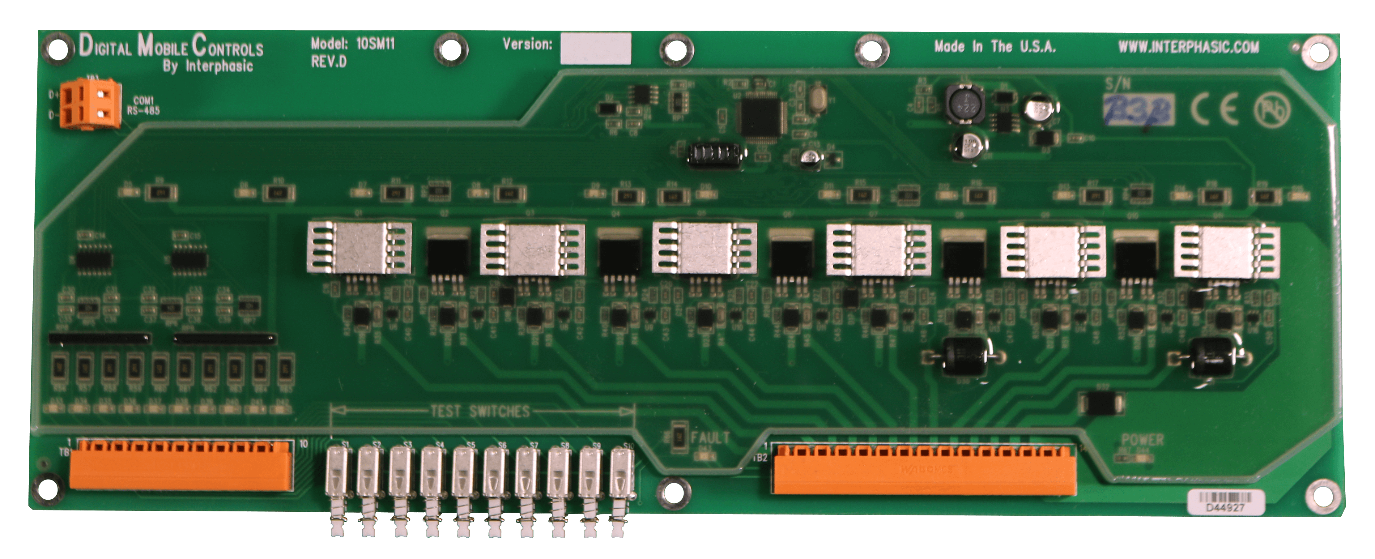
10SM11 CONTROLLER
10 – Digital inputs
11 – High power outputs
10 – Diagnostic test switches
PWM capable outputs
CONTROLLER FEATURES
The 10SM11 controller has been designed to interface with pneumatic, hydraulic or electromechanical devices. This controller will interface with industry standard switches and sensors. All digital mobile controllers come with free programming software and a program template to facilitate fast control program development.
-
Ideally suited to extreme automotive and industrial applications, static or mobile
-
Mechanical locking connectors to resist vibration
-
Rugged heavy duty design with output short proof protection
-
In-System Flash programmable
-
1 PWM capable output at 10 bit resolution, other outputs capable at lower resolution
-
Integrated input, output, fault and power Tell-Tail LED’s providing optical feedback for diagnostic and operational monitoring
-
Push-to-test diagnostic switches
-
Digitally hardened against EMI and ESD
-
Environmentally sealed for extended service life
-
Operating temperature – 40°C to +85°C
-
Operating voltage 9 to 30 VDC
-
Controller size of 12.98″ x 4.79″ x 0.9″
-
Lead-Free design
-
UL 94V-0 Flame Retardant Classification
-
SAE J1455 – Recommended environmental practices for electronic equipment design (Heavy duty trucks)
-
ASAE EP455 – Over voltage and reverse polarity protected
-
SAE J1113 – Recommended practices for shock, vibration and electromagnetic compatibility with immunity to conducted transients on
Electrical Parameters:
- Input resistance: 1.1K Ohms
- Input voltage range: -3 VDC to +30 VDC
- Frequency input: 0 to 1KHz
- Operating voltage: 9 VDC to 30 VDC
- Quiescent current: 19mA
- Operating Temperature: – 40°C to +85°C
- Forced convection required above +55°C at maximum output
- Environmental Protection: Gelatinous silicone conformal coating with mechanical locking connectors
- Output resistance: 0.038 Ohms @ 25°C
- Output current: 5 Amps maximum continuous.
- Outputs can be combined for high power output
- Outputs are short circuit protected and open circuit monitored
- Inductive load protected, repetitive 3 Amp maximum
- Voltage swing: 0V to B+ (Battery Voltage)
- PWM duty cycle: 0 to 100%
- Reverse voltage protected
- 100% CMOS logic for greatest noise immunity
MCU Parameters:
- Microchip RISC PIC16F 8-bit Microcontroller
- High performance Flash Microchip PIC16F872
- 20Mhz = 200nS Fast execution time
- 4 kByte Enhanced Flash memory
- 64 Byte EEPROM
- 128 Byte RAM
- Interrupt driven timing control
- 8 level deep hardware stack
- Brown-out detection circuitry for controller reset
Special MCU Parameters:
-
10-bit PWM module
-
Power-on reset (POR)
-
Power-up timer (PWRT)
-
Watchdog timer (WDT)
-
Power saving sleep mode
-
In-circuit programming
PRODUCT FILES ACCESSORIES
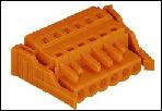
Connector with side locking feature:
10 Pole input connector
P/N CON10W
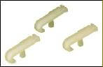
Connector operating lever:
Allows easy insertion of wires into connectors.
Operating lever, 10 per package
P/N CONTW
Controller Mounting Kit:
contains all the standoffs and hardware necessary to securely mount the 10SM11 controller
P/N MK10SM11
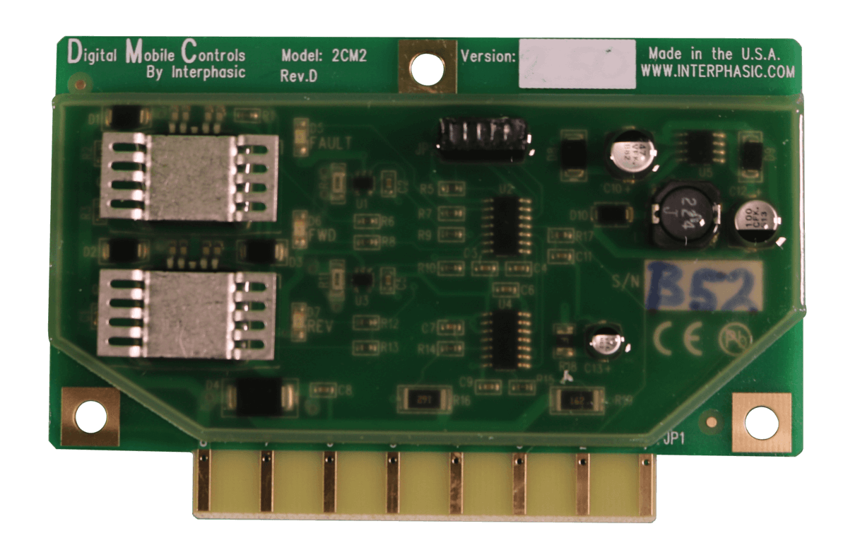
MODEL 2CM2
2 Digital Inputs
2 High Power Outputs
1 Analog Input
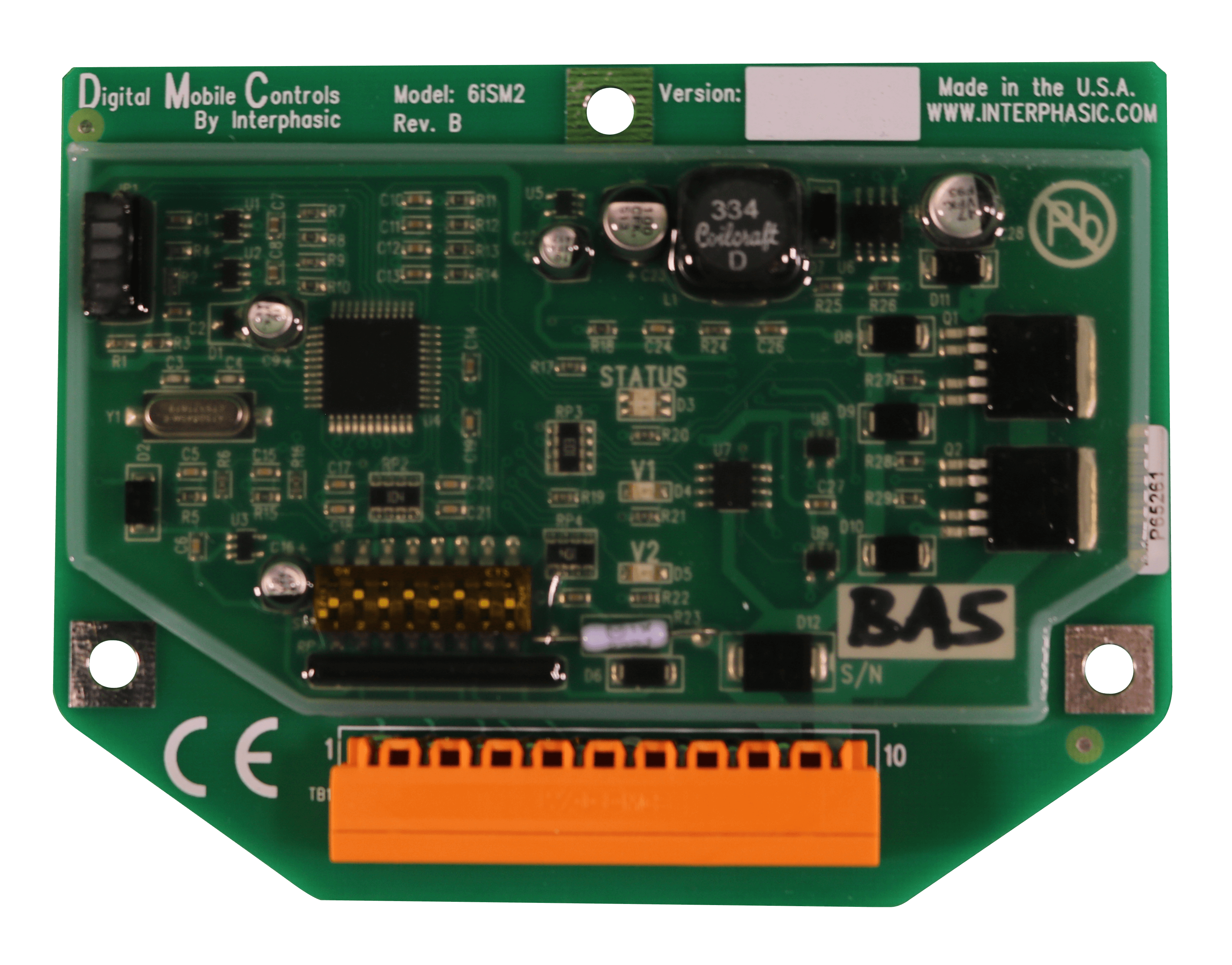
MODEL 6iSM2
6 Digital Inputs
2 High Power Outputs
2 Analog Inputs
MODEL 10SM11
10 Digital Inputs
11 Outputs
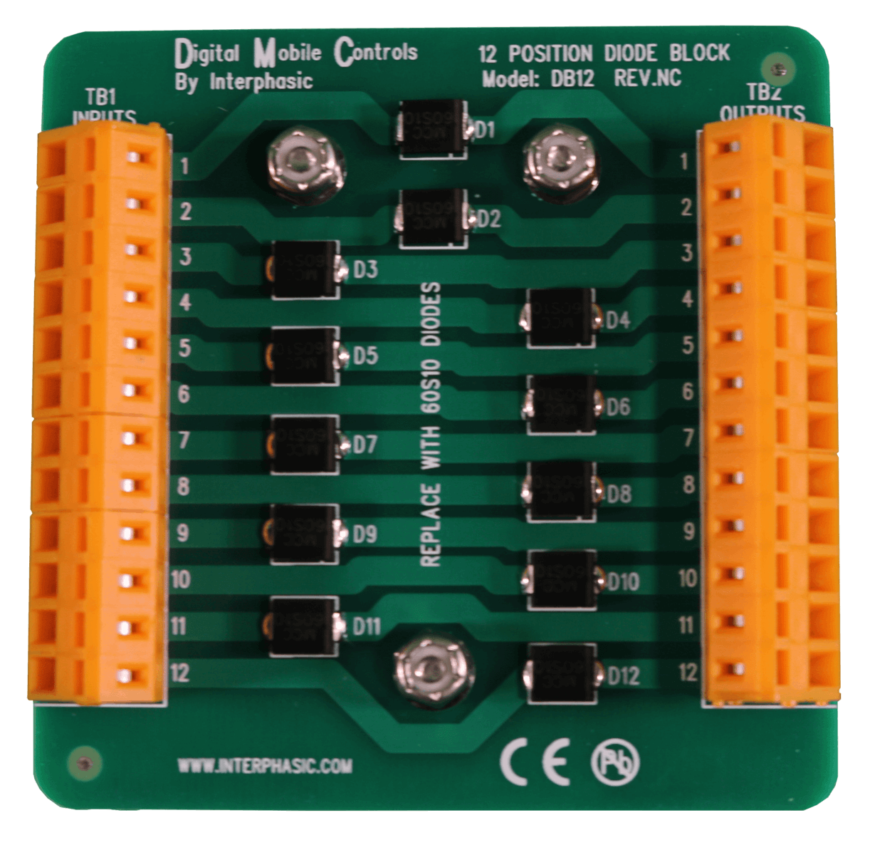
MODEL DB12
12 isolated
6 amp
1000V diode block
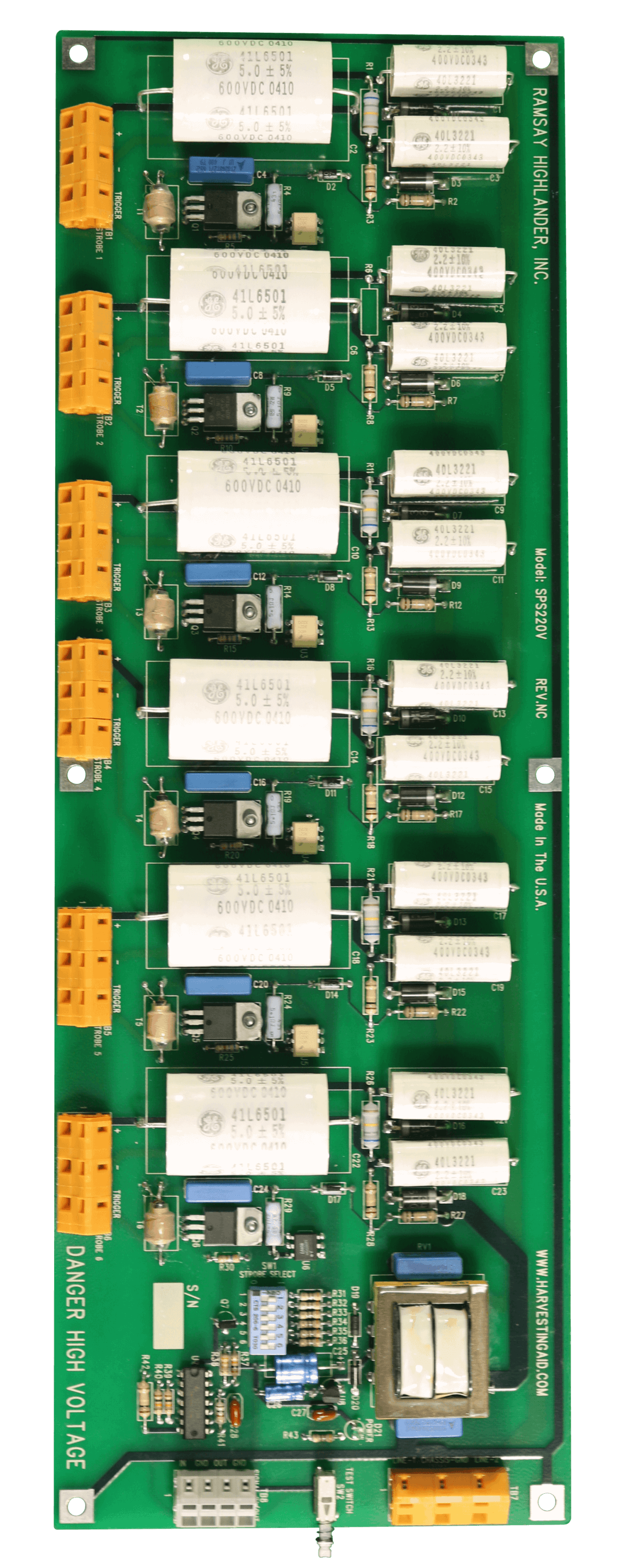
MODEL SPS220V
6 Output Strobe
Selectable Outputs
1.3 Joules FlashEnergy/Output
1 TTL Input Interface
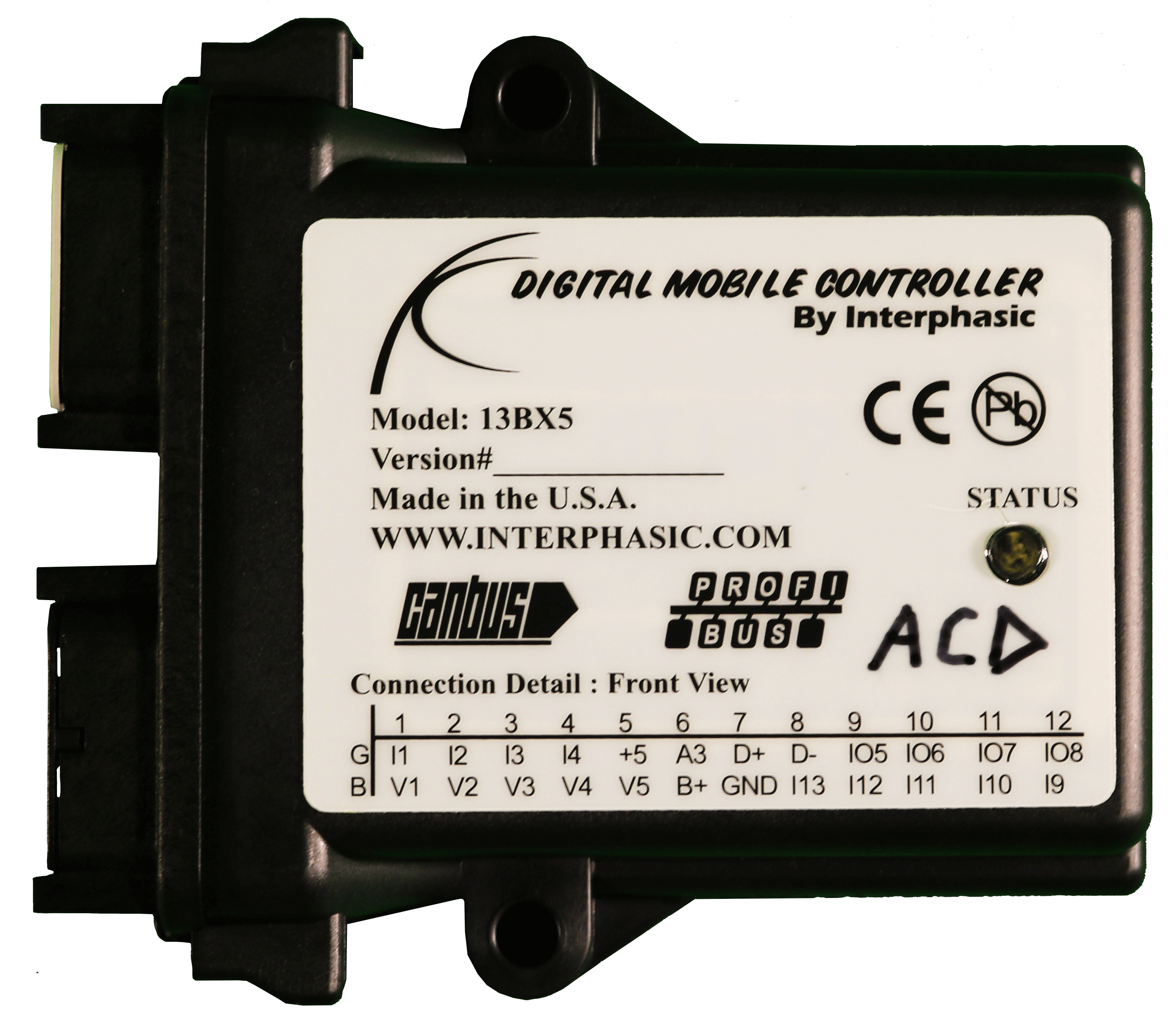
MODEL 13BX5
13 Digital Inputs
2 Analog Inputs
5 Outputs
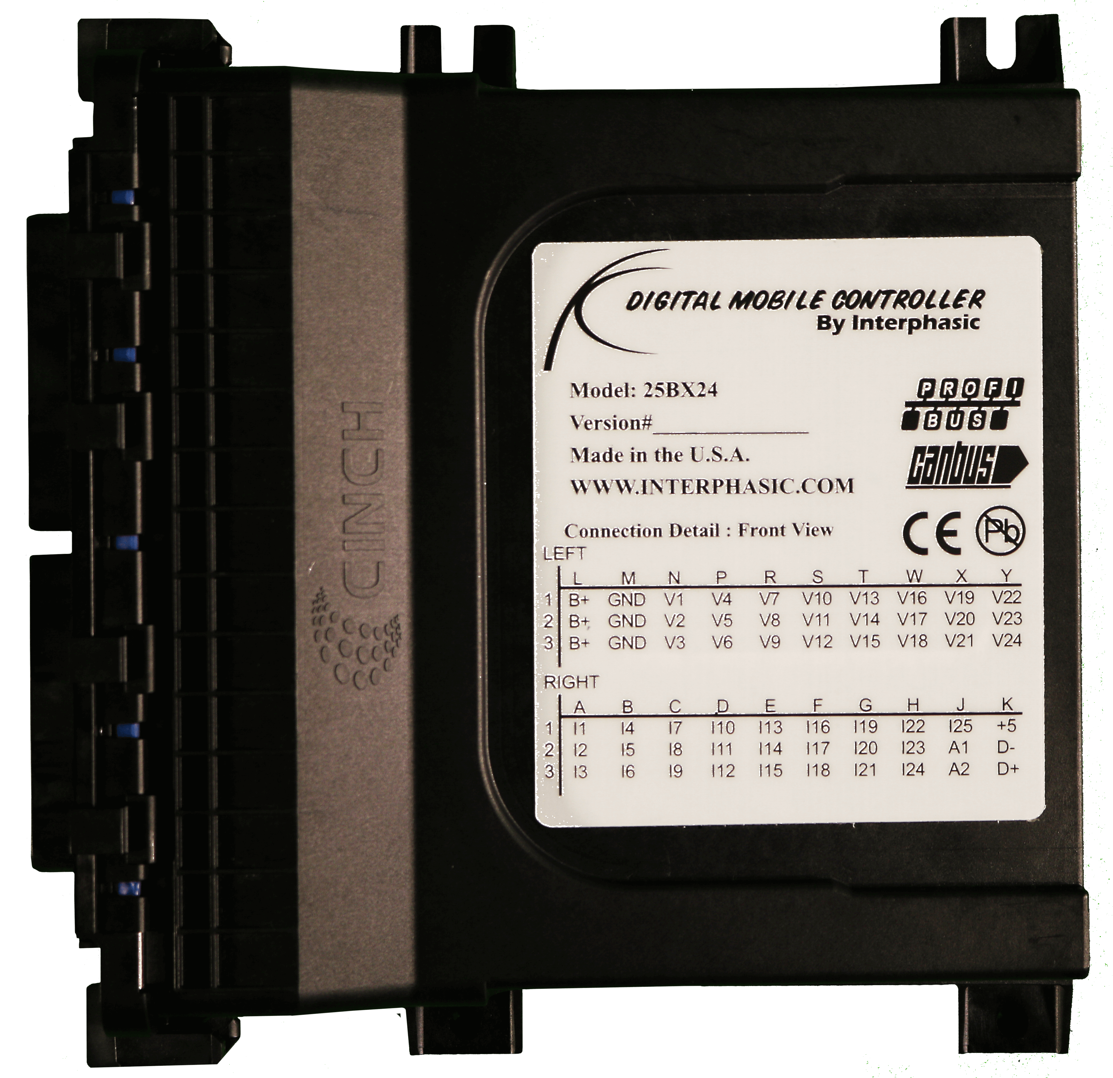
MODEL 25BX24
25 Digital Inputs
2 Analog Inputs
24 Outputs